A Review on Performance Enhancement Techniques for Ambient Vibration Energy Harvesters
![]()
Multimodal Multidirectional Piezoelectric Vibration Free energy Harvester by U-Shaped Structure with Cross-Connected Beams
1
Key Laboratory of Electronic Equipment Structure Pattern, Ministry of Education, Xidian University, Eleven'an 710071, China
2
Shaanxi Primal Laboratory of Industrial Automation, School of Mechanical Engineering, Shaanxi University of Technology, Hanzhong 723001, China
*
Writer to whom correspondence should be addressed.
Academic Editor: Weiqun Liu
Received: 29 January 2022 / Revised: 25 February 2022 / Accustomed: 27 February 2022 / Published: 28 Feb 2022
Abstruse
This paper proposes a multidirectional piezoelectric vibration energy harvester based on an improved U-shaped construction with cross-connected beams. Benefitting from the bi-directional capacity of U-shaped beam and additional angle mode induced by cantankerous-connected configuration, the proposed construction tin well capture the vibrations in 3D infinite at the frequencies lower than 15 Hz. These features are further validated past finite element analyses and theorical formulas. The paradigm is fabricated and the experiments under different conditions are carried out. The results evidence that the proposed harvester can generate favorable voltage and power under multidirectional vibrations at a low operating frequency. Practical applications of charging capacitors and powering a wireless sensor node demonstrate the feasibility of this energy harvester in supplying power for engineering science devices.
1. Introduction
The large-scale use of fossil fuels is causing serious impacts on the global climate in the past few decades. Lowering carbon emission has become a disquisitional task for the global to pursue carbon neutrality. Recently, the issue of harvesting clean and renewable energy from ambient environment has been promoted to provide a possible culling to the conventional solid-land batteries in the booming IoT world. Harvesting energy from ambient vibrations, such every bit winding, man motion, vehicles, machines and buildings, etc., have been reorganized as a feasible solution to supply green energy to wireless sensor nodes [1,ii,3,4,5,six], which tin can be implemented past using electromagnetic [vii,8], electrostatic [9] and piezoelectric [10,eleven] transduction mechanisms to convert mechanical energies into electricity. Among them, piezoelectric vibration energy harvesters (PEVHs) have been highlighted because of its high-power density, ease of implementation and miniaturization [5,12,13]. Typically, a PEVH tin can exist synthetic by a proof mass to capture the vibration, a piezoelectric plate to convert the free energy and a substrate to back up the mass and plate [14]. Though changing the configuration of mass and substrate can arrange PEVH'southward characteristics with diverse energy sources, a PVEH for capturing multidirectional, inconstant ecology vibrations is withal an investable research for reusing wasted ambient environment energy [15].
Lowering the resonant frequency and expanding efficient bandwidth are ii feasible approaches for PVEH to optimize its dynamic properties. The depression resonant frequency can be realized by decreasing the structural stiffness or increasing the weight of proof mass, which is like shooting fish in a barrel just may reduce the long-term reliability of devices [sixteen,17,18]. A more viable strategy is frequency up-conversion mechanism, in which the targeted vibration is captured by a low-frequency structure and transmitted to a loftier-frequency oscillator to trigger its free oscillation [19,twenty]. Consequently, this scheme tin can well capture the low-frequency vibrations and then realize a loftier-frequency, efficient mechanical-electrical conversion. In terms of broadband harvesting, multimodal approach and structural nonlinearity are oft utilized [21,22]. The erstwhile can produce several resonant peaks in a certain frequency range with the helps from segmented beam-mass and multi-unit configurations [23,24]. Then, the nonlinearity, induced past internal force or large deformation, can increase the width of each resonant peak, giving the PVEH a better coverage to the spectrum of volatile vibration [25,26].
For multidirectional harvesting, a direct method is arranging harvesting units for every interesting direction, such as the dandelion-like structure with thirteen piezoelectric cantilevers [27], and the multi-axle structure with coupling magnets [28]. These schemes can effectively capture the input vibrations, but their big, bulky structures volition inevitably lead to a poor volume efficiency. Thus, many efforts are devoted to the development of single-unit device with the ability of capturing vibration in multiple directions. For instance, the structures combining pendulum and cantilever or U-shaped beam have been utilized to etch multidirectional PVEHs [29,30,31], but their heavy ball, large range for ball swing and fixed installation direction may hinder their extensive awarding. A more than compact scheme based on twist piezoelectric beam gives the PVEH a capacity of generating a substantial amount of power under the excitation from any management in the plane in parallel with the beam cross-section [32]. However, its first two resonant frequencies are far from each other and cannot well lucifer the frequency spectrum of ambient vibrations. Consequently, there are still peachy demands on developing multimodal, multidirectional PVEHs that can efficiently harvest energy from excitations in real-world environment.
This paper proposed a PVEH based on an improved U-shaped structure for finer harvesting energy from the multidirectional, inconstant vibrations in daily life. Benefitting from cantankerous-connected beams in the legs of U-shaped construction, this device can sense the stimulations in all the planes that parallel and perpendicular with U grapheme. The adhered piezoelectric plates tin can catechumen stress energy in cross-coupled legs and horizontal axle into electric energy based on the straight piezoelectric upshot. By optimizing the structural dimension, the proposed device can exhibit multi-modal characteristics in the frequency of 2–15 Hz. First, a simulation model of proposed PVEH is established for finite chemical element analysis (FEA), and its static and dynamic characteristics are evaluated. A simplified mode for formulizing the structural resonant frequency is synthetic. And so, an experimental epitome is prepared and tested by a tailored setup to verify the harvesting performances and evidence the design and assay results. Necessary discussions and practical applications are conducted. Finally, main findings and conclusions are summarized.
2. Design and Simulation
2.1. Design and Working Principle
Figure i illustrates the proposed multidirectional PVEH, which is mainly composed of the vertical legs with cross-connected beams (viz. upper beams and lower beams), a horizontal axle between the legs, a proof mass on the center of horizontal beam, and six piezoelectric plates uniformly adhered onto the horizontal and cross-connected beams. The vertical legs and horizontal axle form a U-shaped configuration and play the role of responding to 3D space vibrations. For convenience, a Cartesian coordinate system is also defined in Effigy one, whose axes are respectively parallel to the orthogonally distributed normal directions of horizontal beam and two cross-connected beams. The proposed structure can exist regarded as a conventional U-shaped axle plus two cross-connected upper beams. The conventional U-shaped structure produces two operating modes in vertical and horizontal directions (namely x- and z-centrality directions). The two upper beams can generate a new bending deformation along y-axis, bringing the device more superior performances in harvesting 3D space vibrations. It tin be expected that regardless of the direction of loaded excitation, the flexural deformation of corresponding beams can guarantee the activation of their piezoelectric transducers for energy conversion.
two.ii. Analysis for Proof-of-Concept
For proof-of-concept, a finite chemical element model of the proposed PVEH is congenital. The whole U-shaped substrate is made of contumely, the proof mass is called as steel, and the material of piezoelectric plates is PZT-5A. The mass weight is thirty g, and the dimensions of other parts are listed in Table 1. The continued region (almost 5 mm) in each vertical leg is not included in the valid length of cross-connected beams. The material parameters in FEA are given equally (Elastic modulus, Destiny and Poisson's ratio): 90 GPa, 8540 kg/thousand3 and 0.38 for brass, 60 GPa, 7750 kg/miii, and 0.36 for PZT-5A.
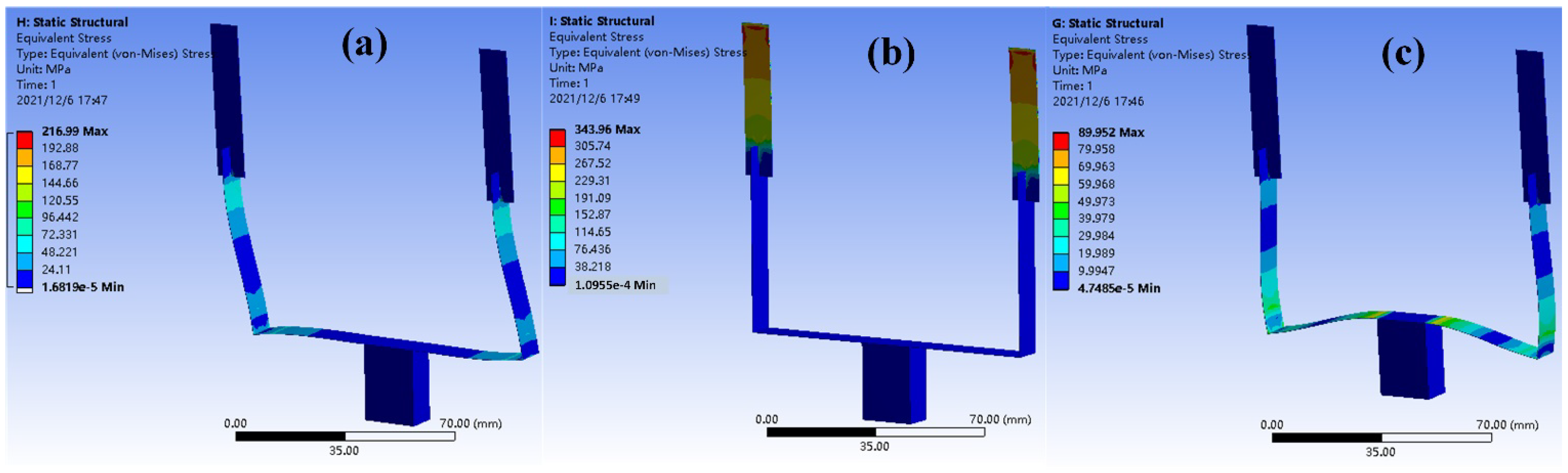
Static analysis is conducted past loading a ane g (one k = ten thou/south2) dispatch to the proposed model. Effigy 2a shows the distribution of equivalent stress nether 10-axis acceleration, in which the corresponding stress mainly concentrates in the lower beam of vertical leg; the y-centrality acceleration can produce a stress concentration nearly the fixed end of upper beam, as shown in Effigy 2b. And so, the maximum stress nether a z-axis dispatch symmetrically distributes near both sides of proof mass. Thus, these 3 stress full-bodied regions are chosen to paste piezoelectric ceramics to maximize the sensed mechanical free energy.
Effigy 3 illustrates the first six-order modes of proposed U-shaped construction, and the resonance happens at the frequencies of two.26 Hz, 10.79 Hz, 13.89 Hz, 23.77 Hz, 36.92 Hz, 49.77 Hz, respectively. The first-order fashion is dominated past the flexural deformation of upper beams, corresponding to the boosted working direction of U-shaped beam. The second-gild and third-gild modes are the horizontal and vertical modes that similar with conventional U beam, while the upper beam does non deform. The fourth-guild mode shows a torsional deformation of upper beams, and the fifth- and sixth-guild modes are dominated past the high-guild modes of conventional U beam. Information technology tin can be seen that the outset three modes are all in the form of flexural deformation and establish the primary working forms of advise PVEH. Meanwhile, the final three torsional deformations are non very suitable for energy harvesting and volition not be concerned in the following sections.
Further, harmonic response assay is conducted to verify the effect from external excitation on the performance of PVEH. The 1 yard sinusoidal acceleration with frequencies ranging from 0–30 Hz are applied in different directions. As shown in Figure 4a, the x-axis acceleration triggers a distinct deformation in the direction of ten-axis at the frequency of 10.79 Hz, and the deformations in other 2 directions are much lower. This farther indicates that the 2nd-guild manner of U-shaped structure effectively undertake the job of collecting vibrations in x-axis direction. Similarly, the distinct deformation triggered past y-axis dispatch is in the direction of y-axis at the frequency of two.26 Hz, dominated by the first-order of structure. Too, the third-guild way of xiii.89 Hz exhibits a amend efficiency when harvesting the z-axis acceleration.
Apropos the FEA results, the first three modes, namely operating modes of proposed PVEH, correspond to the angle deformation of upper beams, first horizontal style and vertical mode of conventional U beam, respectively. Thus, the improved U-shaped construction can be divided into two parts to derive the formulas for its working frequencies. Mostly, the working frequency tin can be expressed as
where Yardi , Mi are the equivalent stiffness and mass of whole structure.
For the first mode, equivalent stiffness Kiu is adamant by the bending of two upper beams and Kiu is dominated past the mass distribution of lower parts, including proof mass, lower beams, and horizontal axle. Thus,
where L is the length of upper beam, m is the mass per unit of measurement length of beams, Mt is mass of proof mass. EI is the flexural rigidity of upper axle, which tin be obtained by analyzing the characteristic of piezoelectric cantilever.
The adjacent ii modes are like with the conventional U-shaped beam. So, the equivalent stiffness and mass for horizontal (indicated by the subscript h) and vertical (indicated by the subscript v) modes are
where EI 1 and EI 2 are the flexural rigidity of lower and horizontal beams, respectively. fifty 1 and 50 2 are their lengths. K 1 and M ii are mass of lower and horizontal beams. αi and βi are the coefficients adamant past structural configuration. More information can be plant in [33].
iii. Prototype and Experimental Setup
An experimental image of proposed PVEH is manufactured, following the process shown in Figure five. The whole U-shaped structure tin be divided into four parts: the horizontal beam and two lower beams in vertical legs, the upper beams, an iron block as proof mass, and six PZT-5A plates. The PZT-5A plate contains an upper silverish electrode, a bottom contumely substrate and a slice of polarized piezoceramics. First, a long brass strip was folded to form a conventional U-shaped beam, which corresponded to the office of horizontal axle and two lower beams of PVEH. Two openings were cut past a scissor at each finish. Then, ii short brass strips for upper beams were prepared, and opening was as well cut at one end of each strip. Next, the brusque brass strips were assembled to the existing U-shaped axle by perpendicularly sticking the openings together, forming a cross connection between the upper and lower beams. Finally, the proof mass and half-dozen PZT-5A plates were adhered onto the U-shaped construction in the adamant region by an insulating gum.
An experimental setup for label is shown in Figure vi. The indicate generator (SDG1020, SIGLENT, Shenzhen, Red china) provides a sinusoidal voltage to the power amplifier (HEA-200C, Foneng, Nanjing, China), which is used to excite the shaker (HEV-200, Foneng, Nanjing, People's republic of china). An oscilloscope (GDS-1072B, GWINSTEK, Suzhou, China) is utilized to measure the voltage generated by PVEH and monitor the acceleration obtained from accelerometer (CA-YD-180, BDHSD, Qinhuangdao, Mainland china). The current source (SD14T03, BDHSD, Qinhuangdao, Red china) is used to power the accelerometer and processing its output point.
To verify the multidirectional harvesting chapters, ii acrylic clampers are designed to adjust the angles betwixt stimulating management and orientation of prototype. The chunk in Figure 7a is used to rotate the PVEH around y-centrality under the vertical vibrations, adjusting the angle betwixt stimulating management and z-axis of PVEH (defined every bit α). α = 0° and 90° bespeak the stimulating management is aligned with z-centrality and x-axis of PVEH. The clamper in Figure 7b is used when the vibration is horizontally loaded. The PVEH is rotated around z-centrality to adapt the angle between stimulating direction and y-axis of PVEH (defined as β). β = 0° and xc° indicate the stimulating management is aligned with 10-axis and y-axis, respectively.
four. Results and Discussions
With the help of experimental setup and rotatable champers, the paradigm is successively stimulated by the vertical and horizontal vibrations with different angles. Due to the symmetry of U-shaped construction, the PVEH volition generate similar response when the angle is beyond 90°, then the experiments are conducted in the range of 0° to 90°. In the experiments, the prototypes are firstly triggered by the loaded vibrations to obtain the curves of open up-circuit voltage versus excitation frequency under dissimilar α or β. Under the vertical vibration, the tertiary-lodge mode of U-shaped structure will be triggered at the beginning, and the lower beam will be bent when α increases. The horizontal vibrations mainly triggered the first- and second-order modes of U-shaped structure when β varies. Then, the power tests are conducted by recording the voltage over the loaded resistors when the devices are stimulated at their optimized frequencies. Last, some applications are demonstrated by charging capacitors and powering a wireless sensor node. All the experiments are conducted at room temperature well-nigh 20 °C and a humidity of 40% RH.
4.1. Experimental Results
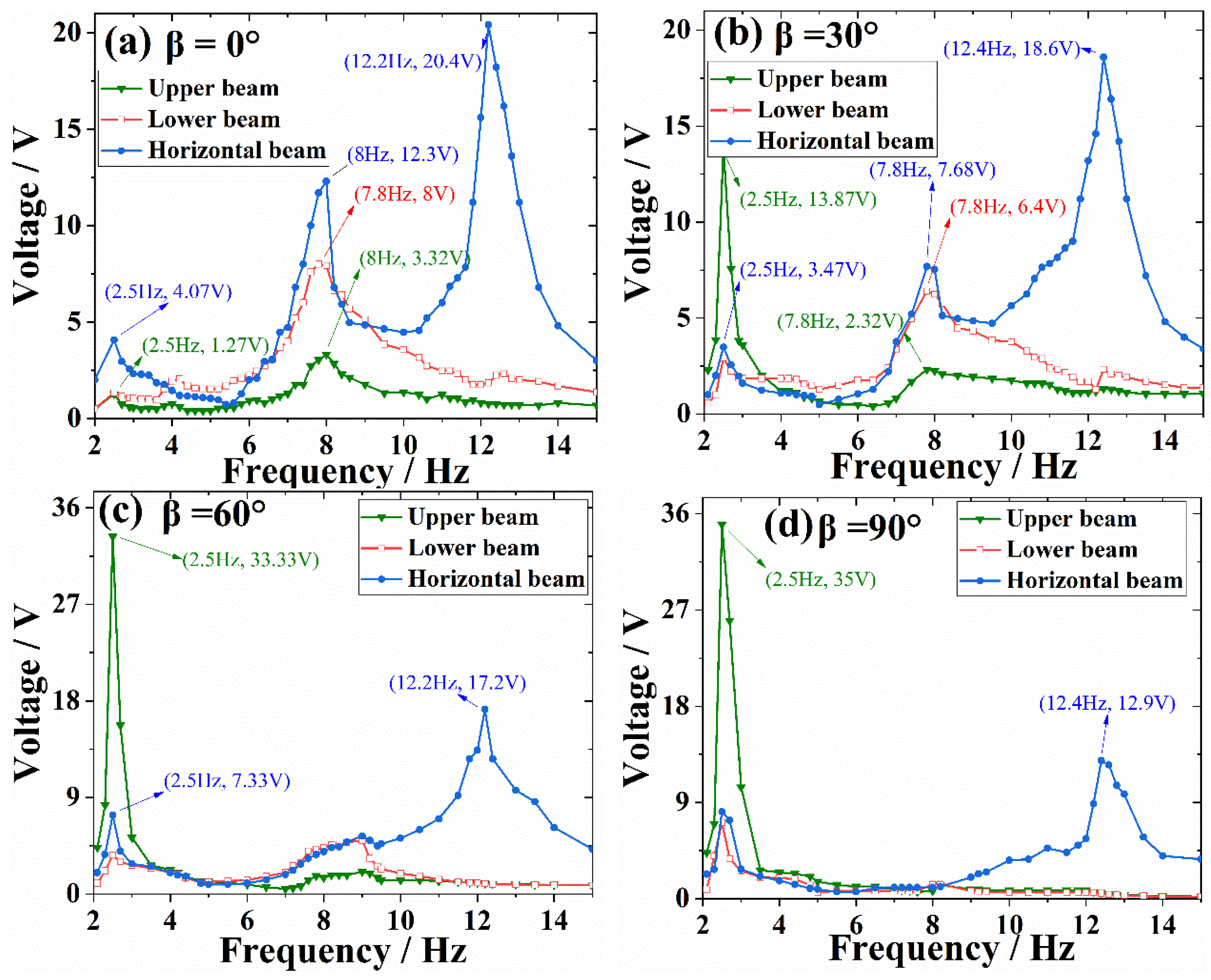
Figure 8 shows the open up-circuit voltage of PVEH with α varying from 0° to 90° when the 1 g acceleration is vertically loaded. When α = 0°, three peaks are generated at the frequency of 2.half-dozen Hz, 9.1 Hz, and 11.iv Hz, which is similar to the simulation results of modal and harmonic response analysis. At 2.6 Hz, the small-scale oscillation of PVEH bends the upper beams, and the lower, and horizontal beams are also deformed by the effect of gravity, whose output voltages are all effectually 4 V. At 9.1 Hz, the structure exhibits a horizontal mode with voltages of half-dozen.56 V for lower beams and 8.00 V for horizontal beam. At 11.iv Hz, the construction exhibits a vertical mode and the horizontal axle is strongly deformed with an output voltage of 56 V. When α = xxx°, the horizontal manner at second peak becomes more intense, inducing a higher voltage of 26.8 V in the lower beam. Meantime, the output voltage of horizontal beam decreases to 37.half-dozen Five at 11.4 Hz, due to the reduction of effective acceleration component. Figure 8c illustrated the circumstance of α = threescore°, in which the voltage of lower beam reaches the value of 44 V, and the voltage of horizontal beam farther decreases to 24.4 V. When α = xc°, the excitation direction is perpendicular to upper beam plane, and the output voltage frequency response is shown in Figure 8d. Except of the 3 resonant peaks corresponding to the results of mode analysis, in that location are boosted mini peaks near 4.iv Hz and 5.8 Hz in the curves of upper and horizontal beams when α = 30°, 60°, and 90°. This may exist attributed to the initial deformation induced past gravity when the prototype is mounted onto the clamper.
To farther investigate the effect of α, the output voltage of different beams at the three resonant peaks, namely 2.6 Hz, 9.i Hz, and 11.4 Hz, are concluded in Effigy 9. When α = 0°, the horizontal axle exhibits a maximum voltage of 56 V at the third resonant peak, corresponding to the mode result in FEA. Equally α increases, the excitation management deviates further from the management of third-order manner, causing a continuous subtract to the voltage at the 3rd-social club resonant frequency. For the voltages at first- and second-order modes, the voltage of lower beam increases at the commencement (α = 0°~threescore°), and then maintains at a relative stable value at larger angles (α > 60°). This phenomenon may be attributed to the interdependence betwixt the deformations of horizontal axle and upper and lower beams, whose vibration modes are the dominators at the start two resonant frequencies. For the upper axle, the largest voltage appears at the 2nd frequency, whose bending manner is gradually triggered when α increases beyond 0°. The bending style of upper beam cannot be activated by the vertical vibrations, and the small output voltages are mainly induced past the interdependence between different beams.
Figure 10 and Figure 11 indicate the voltage results nether the horizontal vibrations. The bending mode of upper beam is activated at the frequency of 2.5 Hz when β increases across 0°, and then the voltage produced by upper beam become larger and larger, reaching its largest value of 35 V when β = 90°. Meanwhile, the horizontal vibrations mainly triggered the higher modes that aforementioned with a conventional U-shaped axle. Therefore, the voltages of lower and horizontal beams are large when β = 0°, and gradually decreases with the increase of β.
The optimal impedance and maximum output power of proposed epitome are also tested. Firstly, the ability is evaluated at the situation of highest output voltage of each axle. The two piezoelectric patches on upper beams are connected in parallel and stimulated by a 0.5 m, two.v Hz horizontal acceleration with β = 90°. Figure 12a shows its output voltage and power under varying load resistance. The optimal load resistance is 730 kΩ and with a maximum power of 314.83 μW. The lower beams are evaluated under the status of 0.five thou, ix.1 Hz vertical vibration, parallelly connected patches and α = 90°. As shown in Figure 12b, the obtained optimal load resistance and maximum power are 690 kΩ and 317.45 μW. The horizontal beam is tested under the condition of 0.v 1000, 11.4 Hz vertical vibration, parallelly connected patches and α = 0°. Effigy 12c illustrates that the optimal load and output power are 440 kΩ and 305.82 μW. And then, the capacity of harvesting multidirectional vibration are also verified past loading a 0.5 g vertical excitation with α = 60° at the second-gild resonance frequency. The results for upper, lower and horizontal beams are (690 kΩ, vii.02 μW), (690 kΩ, 230.09 μW), (690 kΩ, 112.23 μW), respectively. These experimental results indicate that the newly proposed U-shaped construction has good performances in harvesting multidirectional vibrations.
four.ii. Discussions
The resonant frequency is a very important parameter for PVEHs. Herein, a simple comparing is conducted between the frequencies obtained from assay and experiments. The results are shown in Table ii. It can be seen that the frequencies from FEA is a little college than the measured ones. This circumstance can be attributed to the mechanical and electrical damping in the experimental prototype. Similarly, the frequencies from formulas are much higher than the experimental results (about forty% higher), due to the absenteeism of proper damping ratio. Information technology is a hard work to model the mechanical and electrical damping with classical theories, and the obtained formulas may become likewise complex to guide the structural blueprint. Therefore, the work focuses on the undamped condition to link the structural parameters and resonant frequencies. This simplification will inevitably overstate the frequency values. Meantime, the connecting wires, adhesives for fixing PZT plates and proof mass will increase the equivalent mass of whole epitome, which can subtract the resonant frequencies and further expand the departure.
Table iii summarizes and compares some previously reported PVEHs with our proposed device in terms of normalized power density. Information technology can exist seen that the performance of the proposed PVEH has favorable comprehensive performance in frequency, multi-model, power and normalized volumetric power density (NVPD). Meanwhile, compared with the proposed PVEH, virtually 3D PVEHs had difficulty in achieving multiple resonant peaks in a certain frequency for every management. Additionally, the proposed PVEH shows good performance in terms of NVPD compared with the existing multidirectional PVEHs, and the value can reach 0.1115 µW/(mm3giiHz), which is close to many 1D PVEHs. Therefore, the proposed PVEH using improved U-shaped structural as a multidimension, multimodal energy harvesting architecture shows potential for practical applications in the daily environment.
Another critical issue in developing PVEH is the device reliability. Firstly, the structural dimension should exist carefully determined to simultaneously guarantee the harvesting performances and keep the working stress within the allowable range. With the help of FEA software, the stress in brass substrate and piezoelectric plates are all evaluated. Except the stress concentration in some boundaries, the simulated stress is at the level of 50–100 MPa, lower than the extension force of materials. Hundreds of thousands of acceleration cycles take been loaded to the PVEH paradigm during characterization, and no significant attenuation happens in the output voltage. Secondly, the wires for power manual are all simply suspended in air without additional protection, which might be a hidden problem in device reliability. A sudden drag may pause the conducting path and brand the device out of work. Therefore, additional length of wire is reserved in the epitome to provide enough room for motion and drags. This state of affairs is common for many reported experimental prototypes, and may exist improved by using distribution frame and standard connectors.
4.3. Applications
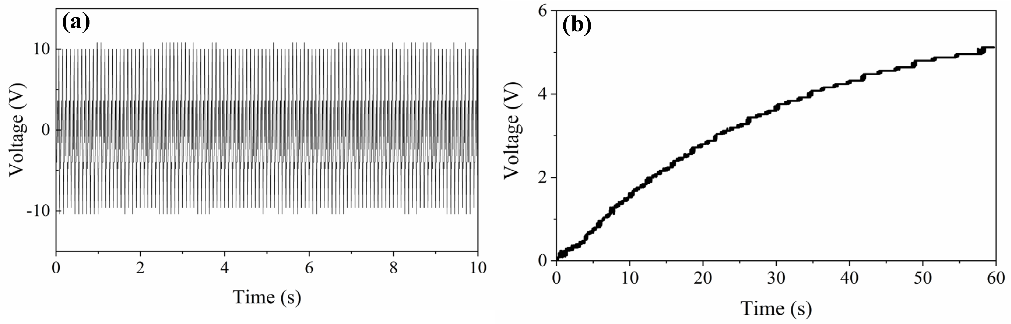
First, the proposed PVEH is triggered by shaker, and the vibration parameters are set according to the vibration in instrument panel of a vehicle [37]. Figure 13 indicates the open-circuit voltage of horizontal axle. Under the sustained vibration, the proposed PVEH can generate a steady voltage nigh 10 Five and charge a 47 μF capacitor to 5 5 in one minute with the assist of rectifier (LTC3588-1).
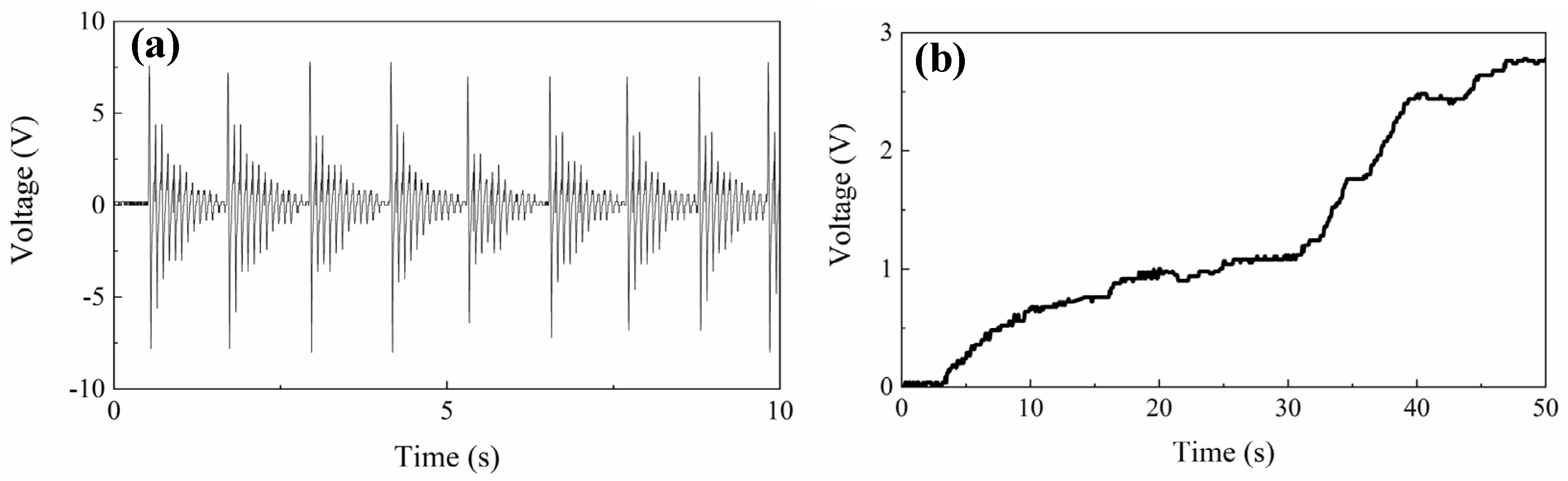
And so, the biomechanical free energy in human walking is harvested by mounting the PVEH at waist. Stamping the feet gently in a frequency about 1 Hz will load a sustained daze stimulation to PVEH. The captured voltage is shown in Effigy 14a, in which a decomposable wave betoken by attenuating costless vibration with a resonant frequency of 10.8 Hz is obtained due to electromechanical coupling and mechanical damping. Every bit shown in Figure 14b, a 22 μF capacitor can exist charged to 2.8 V after 80 steps by dull stamping (0–thirty s) or fast stamping (thirty–lx s).
Last, a wireless sensor node (NRF 52832) based on Bluetooth is continued to the output port of a harvesting circuit (Effigy xv), which manages and stores the output voltage of proposed PVEH. The device is sustainably stimulated by the former mimetic vibration, and the proposed arrangement enables to bulldoze the sensor node and transmit the temperature signal to a cellphone. Considering the existent-time output power of proposed PVEH, the powered wireless sensor node can work well in the situations without continuous task execution, such every bit monitoring the environmental temperature/humidity. Meanwhile, with the help of energy storage devices (e.one thousand., the abovementioned capacitors), the node can still get the required power when there are no vibrations.
5. Conclusions
This paper proposed a U-shaped construction with cantankerous-connected beams for harvesting energy from multidirectional vibrations in daily surround. The multidirectional and multimodal ability of proposed PVEH originates from the combination of bi-directional feature of conventional U-shaped beam and the additional bending direction of cross-connected beams. A finite element simulation reveals the potential advantages of improved structure in low resonant frequency and good responses to vibrations in dissimilar directions. An experimental paradigm is tested by a shaker organisation with the assistance of tailored clampers. The results show that the proposed PVEH can continuously produce favorable electrical power when the vibrations are vertically or horizontally loaded with different orientation angles. Moreover, three resonant frequencies are produced in the range of two–xv Hz, giving the PVEH image a good adaptation to the frequency spectrum of daily vibrations. Capacitors can exist charged past the energies converted from mechanical vibrations and human motions. The stored energy tin can exist used to ability a Bluetooth-based wireless sensor node device. These results reveal that the proposed harvester features multidirectional and multimodal backdrop for the daily vibrations. Moreover, the bereft theorical modelling needs further investigation in future work, particularly on the electromechanical coupling analysis.
Writer Contributions
Conceptualization, Southward.Thou. and Y.L.; methodology, H.Q., X.J. and S.Thousand.; simulation, S.1000. and South.S.; validation, H.Q., S.M., X.J. and S.S.; paradigm S.1000. and P.Westward.; writing—original draft, Southward.M. and Y.L.; writing—review and editing, H.Q. and Y.L; supervision, Y.L. All authors take read and agreed to the published version of the manuscript.
Funding
This work was supported by Natural Scientific discipline Basic Research Plan in Shaanxi Province, China, grant numbers of 2020JQ-309 and 2020JQ-872.
Data Availability Statement
The data presented in this study are available upon asking from the corresponding author. The information are not publicly available due to the intellectual belongings.
Conflicts of Interest
The authors declare no conflict of interest.
References
- Sarker, K.R.; Julai, Southward.; Sabri, G.F.Yard.; Said, S.M.; Islam, M.1000.; Tahir, 1000. Review of piezoelectric energy harvesting system and application of optimization techniques to enhance the functioning of the harvesting system. Sens. Actuators A Phys. 2019, 300, 111634. [Google Scholar] [CrossRef]
- Liu, Y.; Wang, H.; Zhao, W.; Zhang, M.; Qin, H.; Xie, Y. Flexible, Stretchable Sensors for Wearable Health Monitoring: Sensing Mechanisms, Materials, Fabrication Strategies and Features. Sensors 2018, 18, 645. [Google Scholar] [CrossRef] [PubMed]
- Ong, Z.C.; Ooi, Y.X.; Khoo, S.Y.; Huang, Y.H. Two-stage multi-modal organization for depression frequency and wide bandwidth vibration free energy harvesting. Measurement 2020, 149, 106981. [Google Scholar] [CrossRef]
- Wang, J.; Geng, 50.; Ding, L.; Zhu, H.; Yurchenko, D. The state-of-the-art review on energy harvesting from menses-induced vibrations. Appl. Energy 2020, 267, 114902. [Google Scholar] [CrossRef]
- Zhao, L.-C.; Zou, H.-X.; Yan, G.; Liu, F.-R.; Tan, T.; Wei, K.-X.; Zhang, W.-Thousand. Magnetic coupling and flextensional amplification mechanisms for high-robustness ambient wind energy harvesting. Energy Convers. Manag. 2019, 201, 112166. [Google Scholar] [CrossRef]
- Wang, J.; Zhou, South.; Zhang, Z.; Yurchenko, D. High-performance piezoelectric wind free energy harvester with Y-shaped attachments. Energy Convers. Manag. 2019, 181, 645–652. [Google Scholar] [CrossRef]
- Fan, Thousand.; Cai, M.; Wang, F.; Tang, Fifty.; Liang, J.; Wu, Y.; Qu, H.; Tan, Q. A string-suspended and driven rotor for efficient ultra-low frequency mechanical energy harvesting. Free energy Convers. Manag. 2019, 198, 111820. [Google Scholar] [CrossRef]
- Miao, M.; Fang, S.; Wang, S.; Zhou, S. A depression-frequency rotational electromagnetic energy harvester using a magnetic plucking mechanism. Appl. Energy 2022, 305, 117838. [Google Scholar] [CrossRef]
- Zhang, Y.; Wang, T.; Zhang, A.; Peng, Z.; Luo, D.; Chen, R.; Wang, F. Electrostatic energy harvesting device with dual resonant structure for wideband random vibration sources at depression frequency. Rev. Sci. Instrum. 2016, 87, 125001. [Google Scholar] [CrossRef]
- He, L.; Zhao, D.; Li, Due west.; Wu, 10.; Cheng, G. A dual piezoelectric energy harvester with contact and not-contact driven by inertial bike. Mech. Syst. Signal Process. 2021, 146, 106994. [Google Scholar] [CrossRef]
- Chen, Chiliad.; Gao, F.; Liu, Z.; Liao, W.-H. A nonlinear M-shaped tri-directional piezoelectric energy harvester. Smart Mater. Struct. 2021, 30, 045017. [Google Scholar] [CrossRef]
- Yang, Z.; Zhou, S.; Zu, J.; Inman, D. High-Performance Piezoelectric Energy Harvesters and Their Applications. Joule 2018, ii, 642–697. [Google Scholar] [CrossRef]
- Liang, H.; Hao, Yard.; Olszewski, O.Z. A review on vibration-based piezoelectric energy harvesting from the aspect of compliant mechanisms. Sens. Actuators A Phys. 2021, 331, 112743. [Google Scholar] [CrossRef]
- Yildirim, T.; Ghayesh, M.H.; Li, West.; Alici, G. A review on performance enhancement techniques for ambient vibration energy harvesters. Renew. Sustain. Energy Rev. 2017, 71, 435–449. [Google Scholar] [CrossRef]
- Tran, Due north.; Ghayesh, M.H.; Arjomandi, K. Ambient vibration energy harvesters: A review on nonlinear techniques for operation enhancement. Int. J. Eng. Sci. 2018, 127, 162–185. [Google Scholar] [CrossRef]
- Wang, H.; Li, B.; Liu, Y.; Zhao, Due west. Low-frequency, broadband piezoelectric vibration free energy harvester with folded trapezoidal beam. Rev. Sci. Instrum. 2019, 90, 035001. [Google Scholar] [CrossRef] [PubMed]
- Li, P.; Liu, Y.; Wang, Y.; Luo, C.; Li, G.; Hu, J.; Liu, W.; Zhang, Due west. Low-frequency and wideband vibration energy harvester with flexible frame and interdigital structure. AIP Adv. 2015, 5, 047151. [Google Scholar] [CrossRef]
- Cha, Y. Energy harvesting using flexible piezoelectric materials from human walking motion: Theoretical analysis. J. Intell. Mater. Syst. Struct. 2017, 28, 3006–3015. [Google Scholar] [CrossRef]
- Wu, Y.; Li, S.; Fan, Yard.; Ji, H.; Qiu, J. Investigation of an ultra-low frequency piezoelectric energy harvester with high frequency up-conversion factor caused by internal resonance mechanism. Mech. Syst. Point Process. 2022, 162, 108038. [Google Scholar] [CrossRef]
- Pyo, S.; Kwon, D.-Southward.; Ko, H.-J.; Eun, Y.; Kim, J. Frequency upward-Conversion Hybrid Energy Harvester Combining Piezoelectric and Electromagnetic Transduction Mechanisms. Int. J. Precis. Eng. Manuf.-Green Technol. 2022, nine, 241–251. [Google Scholar] [CrossRef]
- Wang, Z.; Li, T.; Du, Y.; Yan, Z.; Tan, T. Nonlinear broadband piezoelectric vibration free energy harvesting enhanced by inter-well modulation. Energy Convers. Manag. 2021, 246, 114661. [Google Scholar] [CrossRef]
- Wang, Z.; Du, Y.; Li, T.; Yan, Z.; Tan, T. A flute-inspired broadband piezoelectric vibration energy harvesting device with mechanical intelligent design. Appl. Energy 2021, 303, 117577. [Google Scholar] [CrossRef]
- Jiang, W.; Wang, 50.; Zhao, L.; Luo, Grand.; Yang, P.; Ning, S.; Lu, D.; Lin, Q. Modeling and design of 5-shaped piezoelectric vibration energy harvester with stopper for low-frequency broadband and shock excitation. Sens. Actuators A Phys. 2021, 317, 112458. [Google Scholar] [CrossRef]
- Zhao, Fifty.; Zhou, S. Tunable multi-source free energy harvesting via frequency selective structures. Eng. Res. Limited 2019, ane, 015001. [Google Scholar] [CrossRef]
- Qin, Y.; Wang, S.; Wei, T.; Chen, R. A wide band nonlinear dual piezoelectric cantilever energy harvester coupled past origami. Smart Mater. Struct. 2021, 30, 025025. [Google Scholar] [CrossRef]
- Daqaq, M.F.; Masana, R.; Erturk, A.; Dane Quinn, D. On the Office of Nonlinearities in Vibratory Energy Harvesting: A Critical Review and Discussion. Appl. Mech. Rev. 2014, 66, 040801. [Google Scholar] [CrossRef]
- Chen, R.; Ren, L.; Xia, H.; Yuan, 10.; Liu, X. Energy harvesting performance of a dandelion-like multi-directional piezoelectric vibration energy harvester. Sens. Actuators A Phys. 2015, 230, 1–eight. [Google Scholar] [CrossRef]
- Wang, H.; Hu, F.; Wang, One thousand.; Liu, Y.; Zhao, W. 3-dimensional piezoelectric free energy harvester with spring and magnetic coupling. Appl. Phys. Lett. 2017, 110, 163905. [Google Scholar] [CrossRef]
- Wu, Y.; Qiu, J.; Zhou, S.; Ji, H.; Chen, Y.; Li, S. A piezoelectric leap pendulum oscillator used for multi-directional and ultra-low frequency vibration energy harvesting. Appl. Free energy 2018, 231, 600–614. [Google Scholar] [CrossRef]
- Xu, J.; Tang, J. Multi-directional energy harvesting by piezoelectric cantilever-pendulum with internal resonance. Appl. Phys. Lett. 2015, 107, 213902. [Google Scholar] [CrossRef]
- Mo, Southward.; Liu, Y.; Shang, S.; Wang, H.; Yang, K. Tri-directional piezoelectric energy harvester based on U-shaped beam-pendulum structure. Rev. Sci. Instrum. 2021, 92, 015002. [Google Scholar] [CrossRef] [PubMed]
- Hu, Thou.; Liang, J.; Lan, C.; Tang, L. A twist piezoelectric axle for multi-directional energy harvesting. Smart Mater. Struct. 2020, 29, 11LT01. [Google Scholar] [CrossRef]
- Yang, Y.; Wu, H.; Soh, C.K. Experiment and modeling of a 2-dimensional piezoelectric energy harvester. Smart Mater. Struct. 2015, 24, 125011. [Google Scholar] [CrossRef]
- Brenes, A.; Morel, A.; Gibus, D.; Yoo, C.S.; Gasnier, P.; Lefeuvre, East.; Badel, A. Big-bandwidth piezoelectric energy harvesting with frequency-tuning synchronized electric accuse extraction. Sens. Actuators A Phys. 2020, 302, 111759. [Google Scholar] [CrossRef]
- Wang, L.; Ding, J.; Jiang, Z.; Luo, Yard.; Zhao, L.; Lu, D.; Yang, Ten.; Ryutaro, Yard. A packaged piezoelectric vibration free energy harvester with loftier power and broadband characteristics. Sens. Actuators A Phys. 2019, 295, 629–636. [Google Scholar] [CrossRef]
- Ju, South.; Ji, C.-H. Bear upon-based piezoelectric vibration energy harvester. Appl. Energy 2018, 214, 139–151. [Google Scholar] [CrossRef]
- Roundy, Due south.; Wright, P.G.; Rabaey, J. A study of low level vibrations as a power source for wireless sensor nodes. Comput. Commun. 2003, 26, 1131–1144. [Google Scholar] [CrossRef]
Figure one. The proposed U-shaped construction with cross-connected beams.
Figure 1. The proposed U-shaped structure with cantankerous-connected beams.
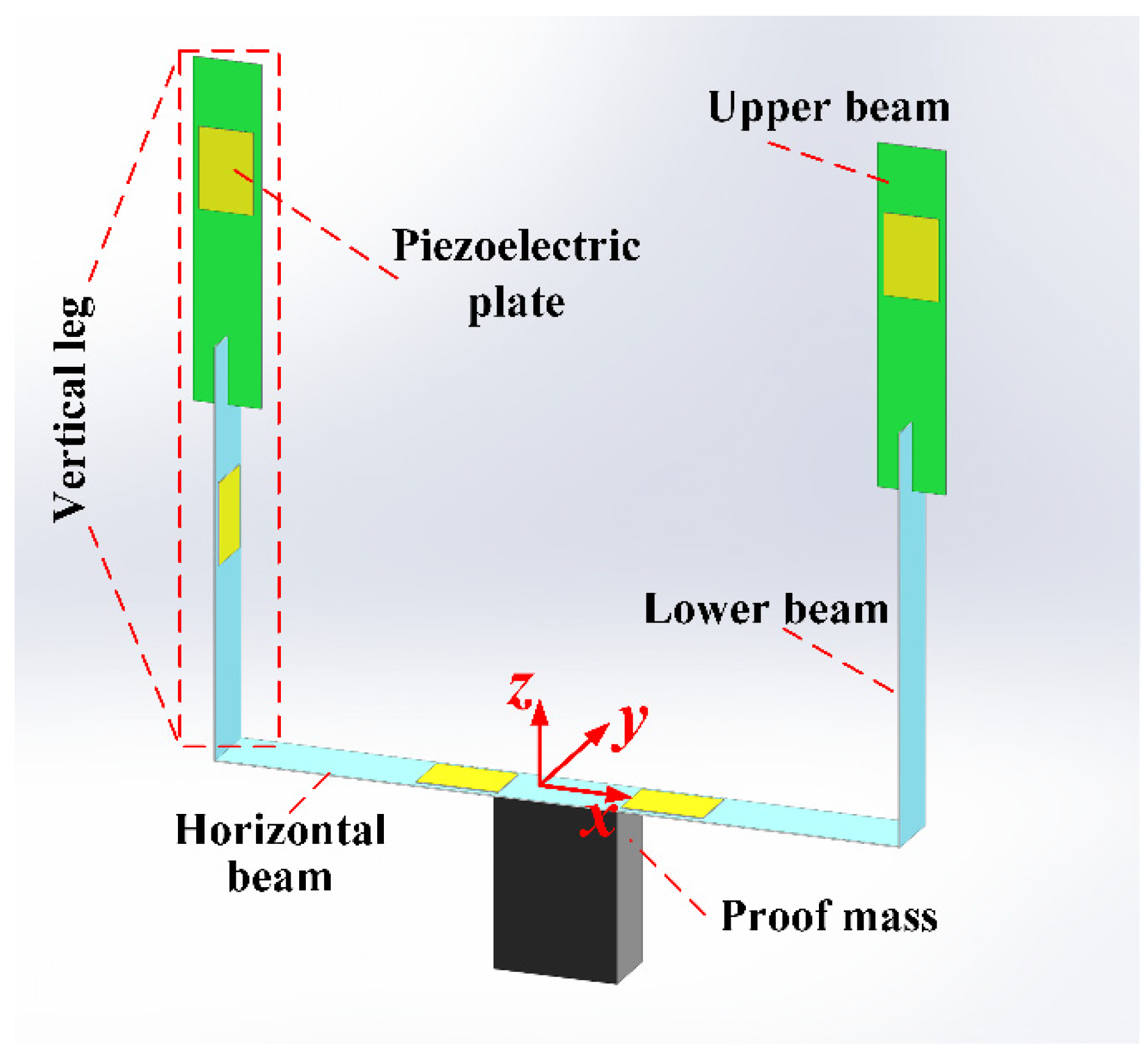
Figure two. The stress distribution in the proposed U-shaped structure when stimulated by (a) x-axis, (b) y-axis, and (c) z-axis accelerations.
Figure 2. The stress distribution in the proposed U-shaped structure when stimulated by (a) ten-axis, (b) y-axis, and (c) z-axis accelerations.
Effigy 3. The beginning 6 modes of proposed U-shaped structure.
Figure 3. The first 6 modes of proposed U-shaped construction.
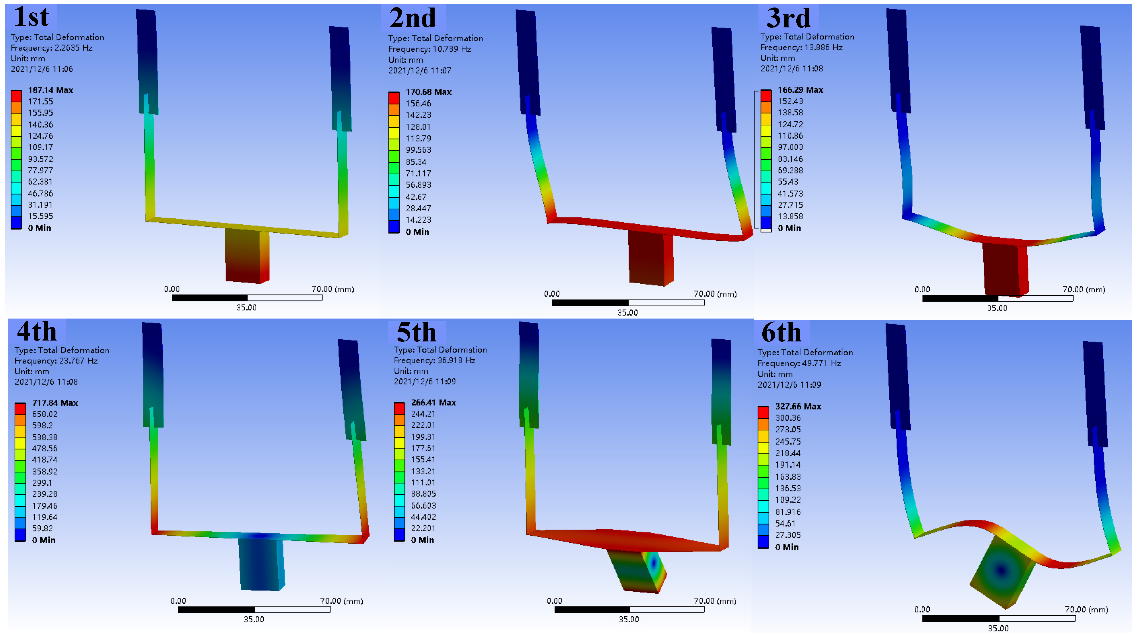
Figure 4. The deformations from harmonic response analysis when the U-shaped structure excited by (a) x-centrality, (b) y-axis, and (c) z-axis accelerations.
Figure 4. The deformations from harmonic response assay when the U-shaped construction excited by (a) 10-centrality, (b) y-centrality, and (c) z-centrality accelerations.
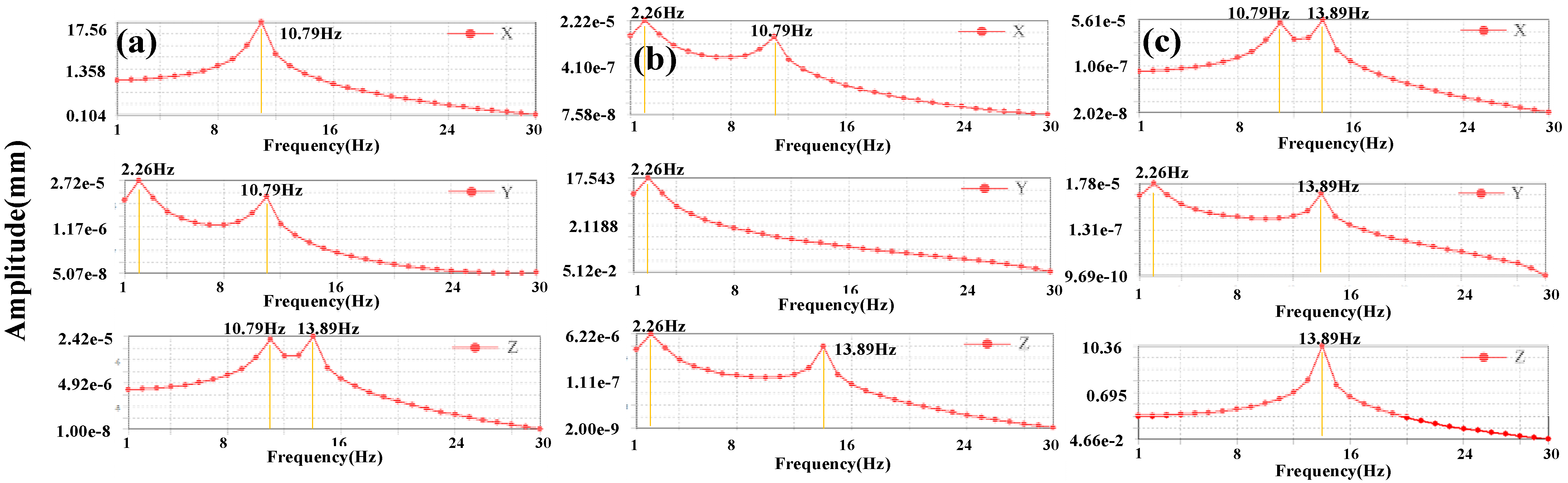
Figure 5. Manufacturing procedure for the proposed PVEH.
Figure 5. Manufacturing procedure for the proposed PVEH.
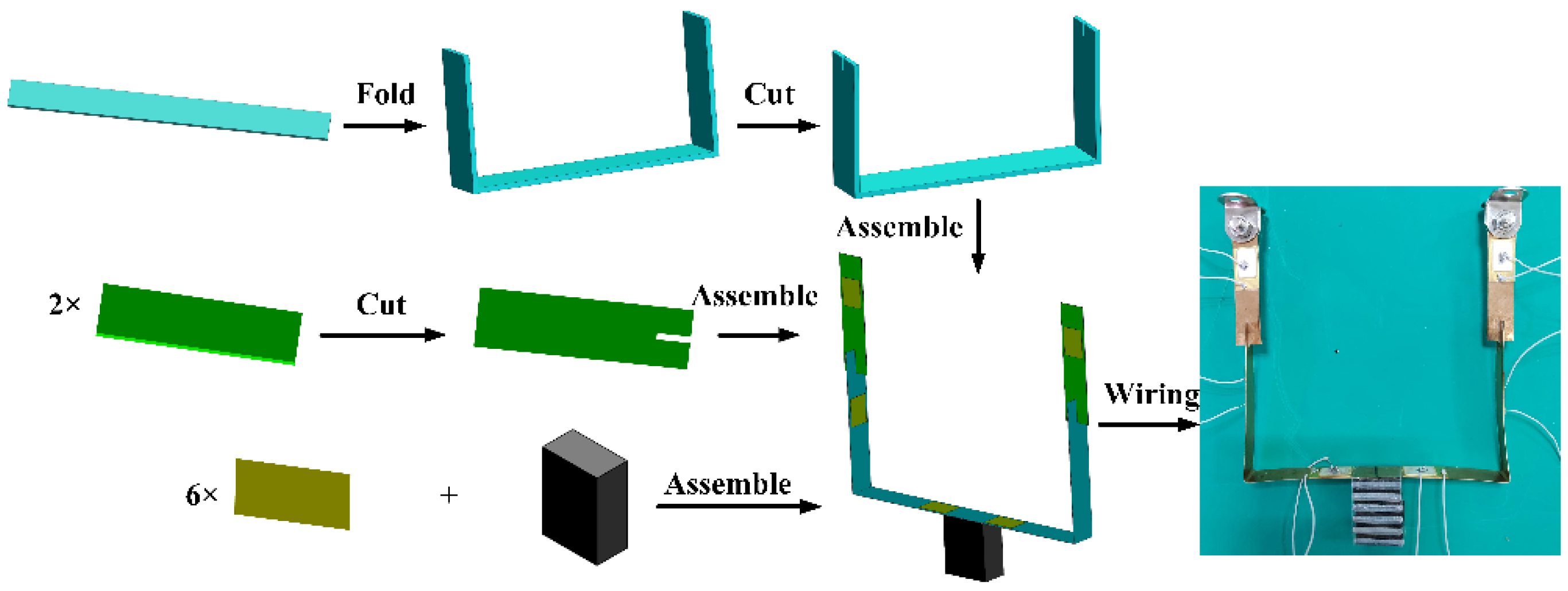
Figure six. Experimental setup for characterization.
Figure 6. Experimental setup for characterization.
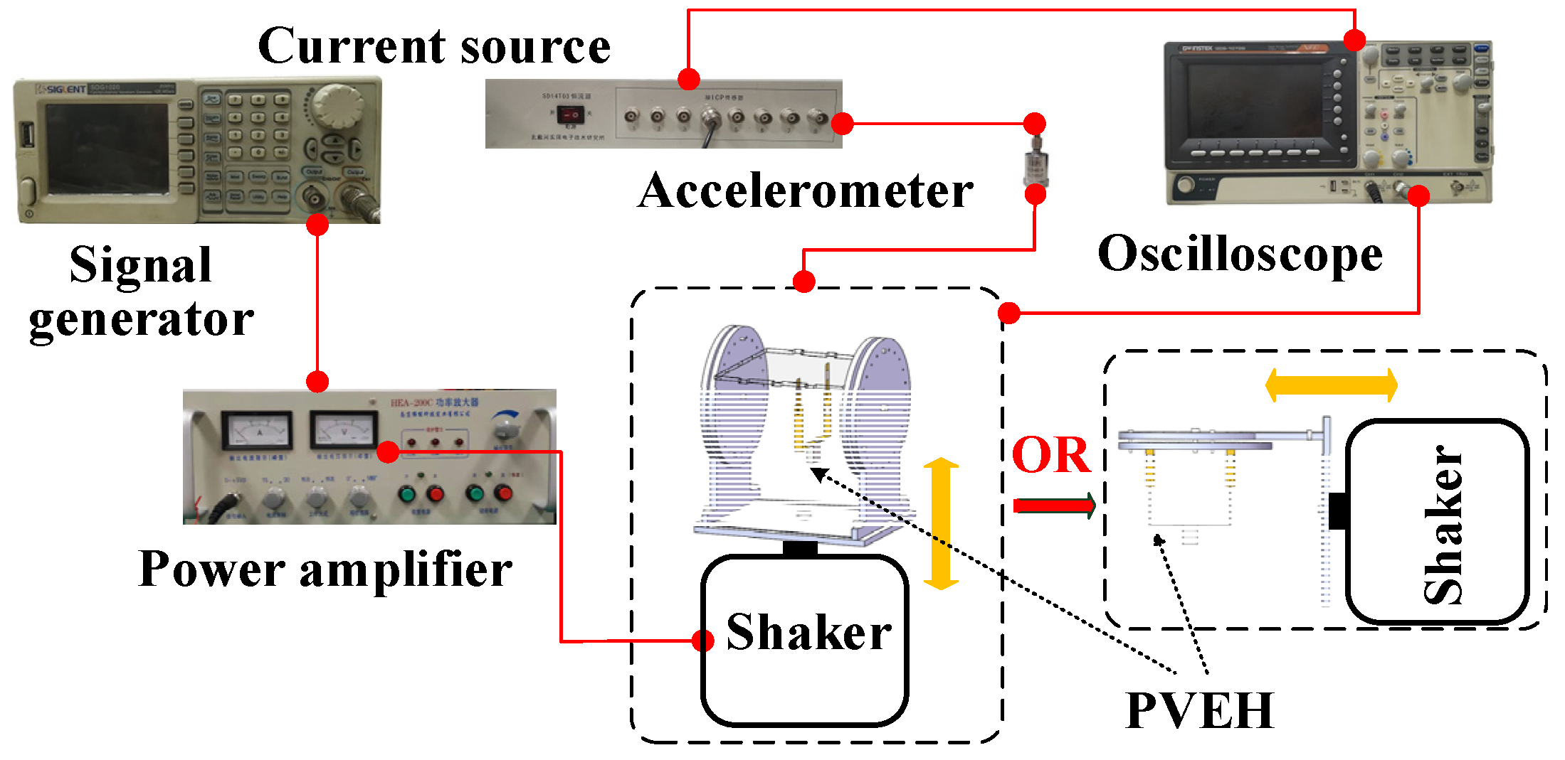
Figure vii. Tailored clampers for (a) vertical and (b) horizontal vibrations.
Figure vii. Tailored clampers for (a) vertical and (b) horizontal vibrations.
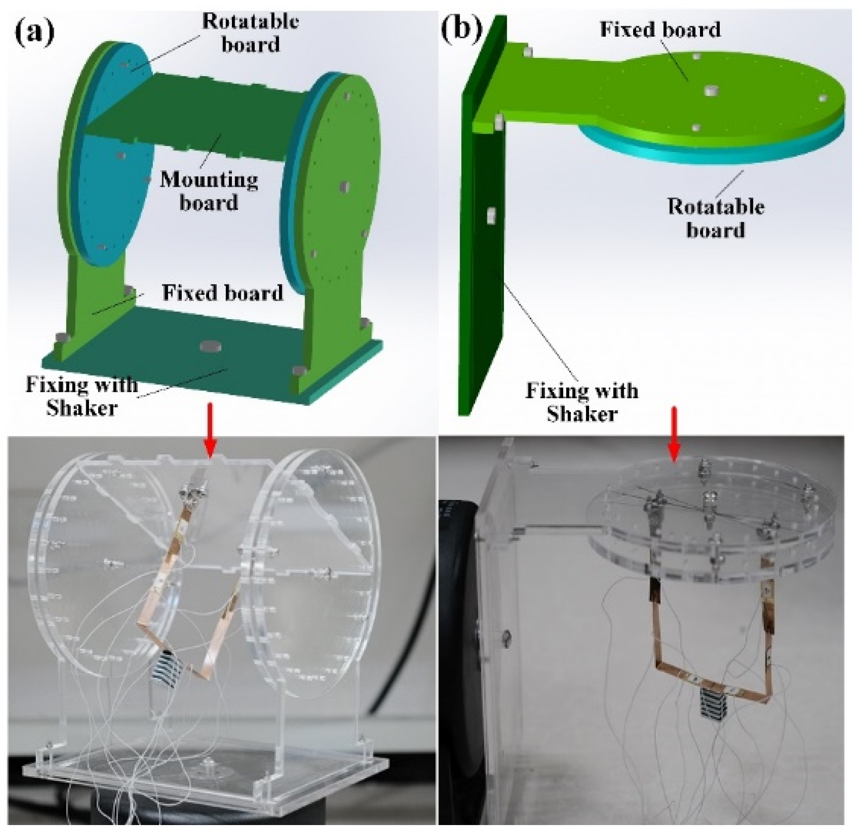
Figure 8. Open up-excursion voltage versus frequency under vertical excitation with unlike α.
Figure 8. Open-circuit voltage versus frequency under vertical excitation with different α.
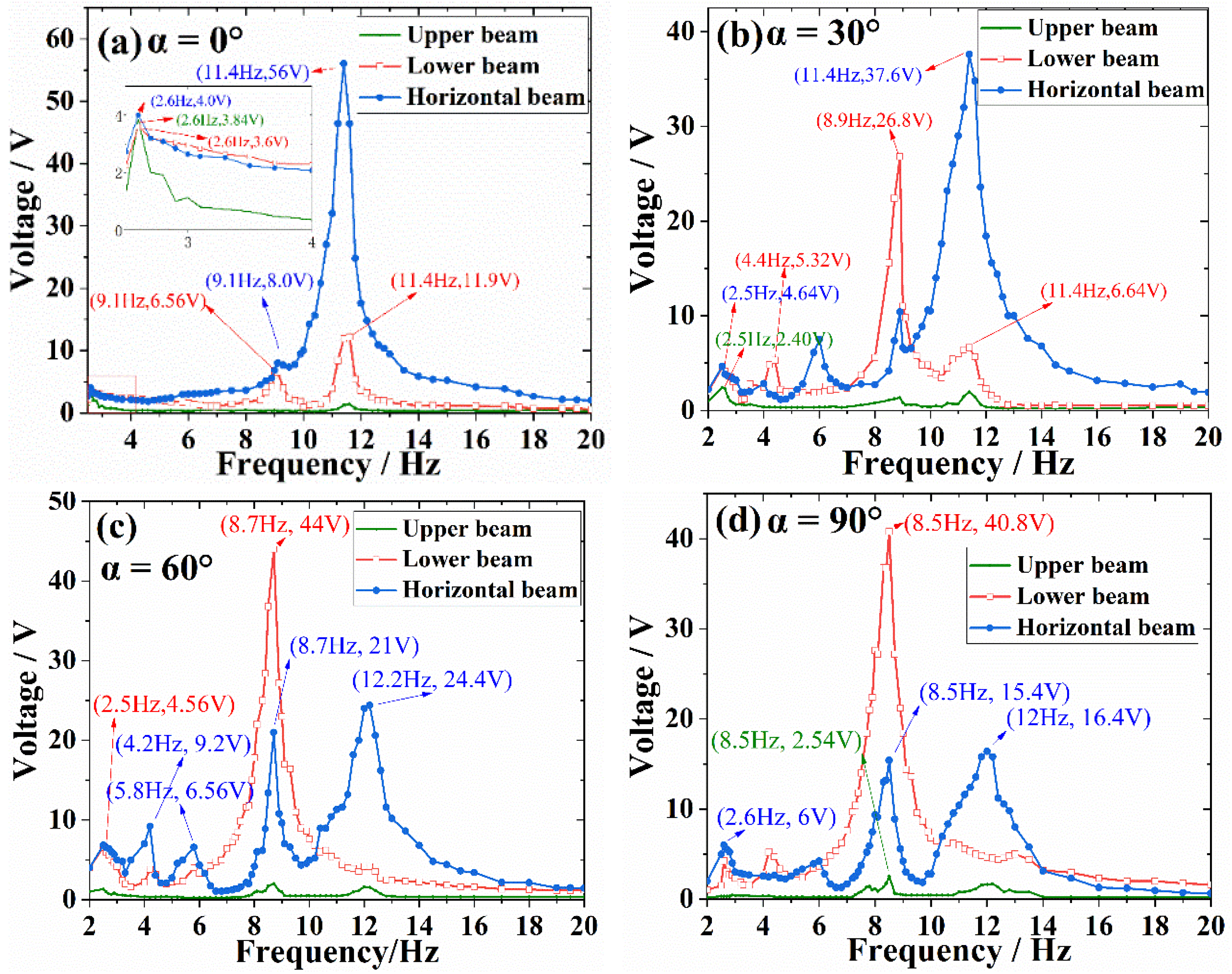
Figure ix. Output voltage of different beams versus α at the first iii resonant frequencies: (a) upper beam, (b) horizontal beam, and (c) lower beam.
Figure ix. Output voltage of different beams versus α at the commencement three resonant frequencies: (a) upper beam, (b) horizontal beam, and (c) lower axle.
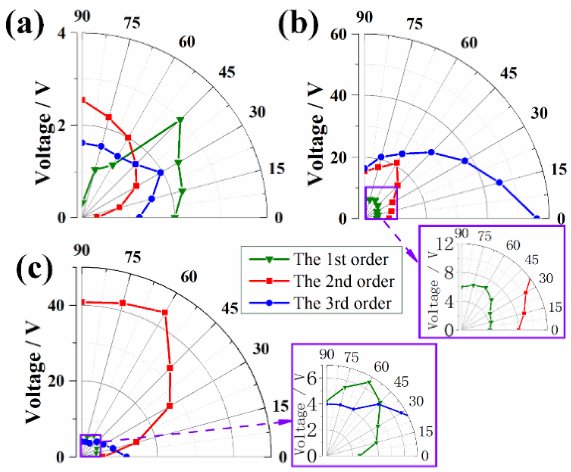
Figure 10. Open up-circuit voltage versus frequency nether horizontal excitation with dissimilar β.
Figure 10. Open up-circuit voltage versus frequency nether horizontal excitation with different β.
Effigy xi. Output voltage of different beams versus β at the starting time 3 resonant frequencies: (a) upper beam, (b) horizontal beam, and (c) lower axle.
Effigy eleven. Output voltage of dissimilar beams versus β at the offset 3 resonant frequencies: (a) upper beam, (b) horizontal axle, and (c) lower beam.
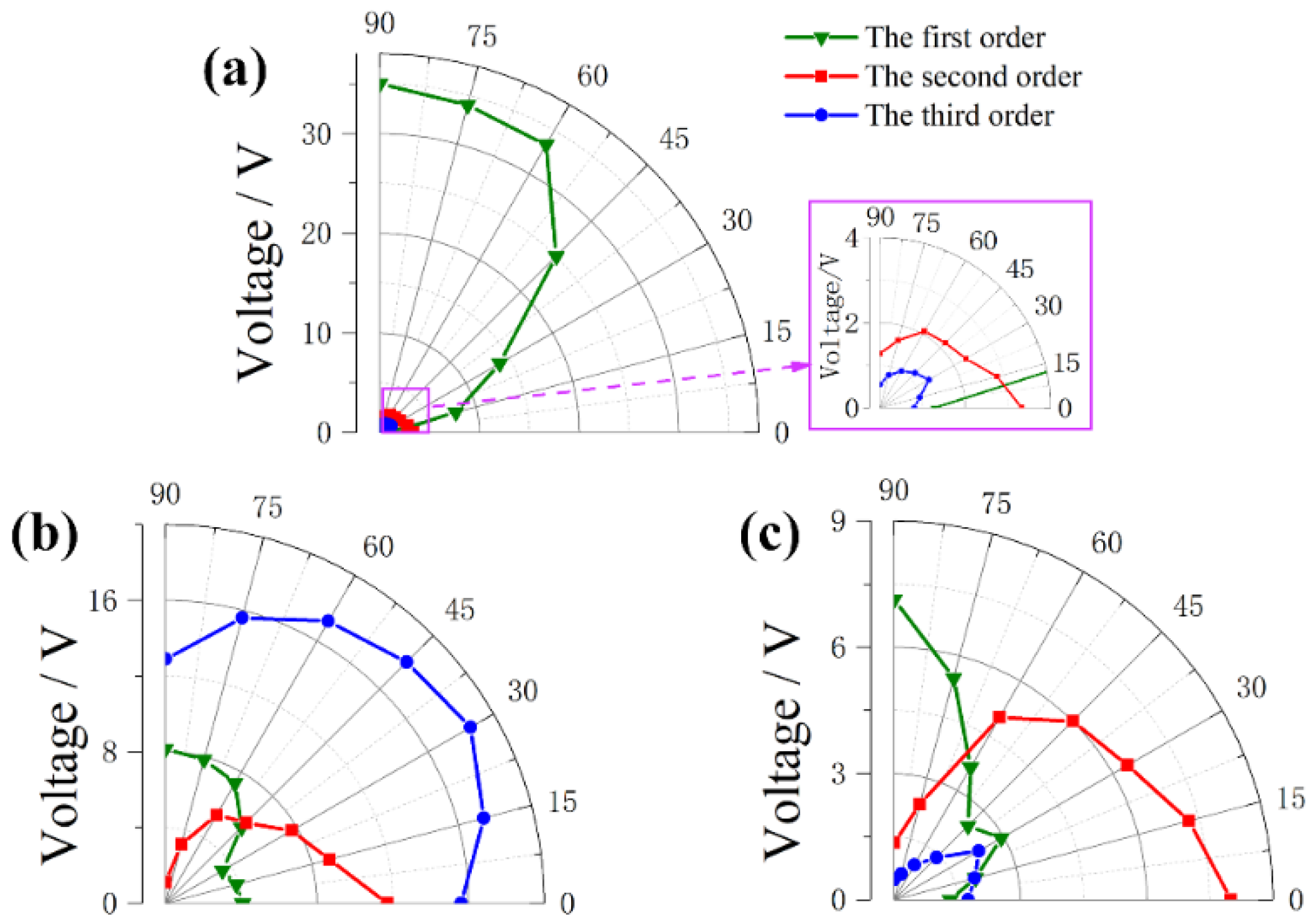
Figure 12. Output ability versus loaded resistance under the maximum voltage for (a) upper beam, (b) lower beam and (c) horizontal beam.
Figure 12. Output ability versus loaded resistance nether the maximum voltage for (a) upper axle, (b) lower axle and (c) horizontal axle.
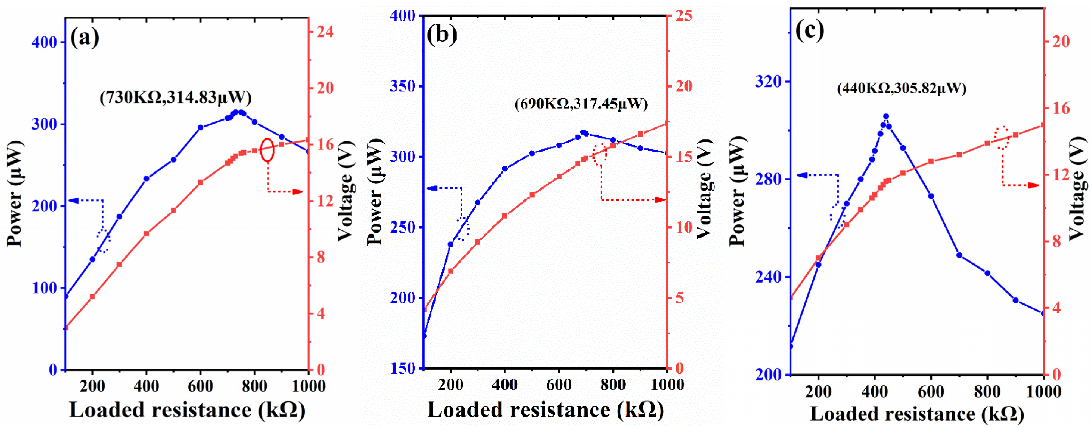
Figure xiii. Applying proposed PVEH in harvesting sustained vibration. (a) Output voltage of proposed PVEH; (b) The voltage over charged capacitor.
Effigy xiii. Applying proposed PVEH in harvesting sustained vibration. (a) Output voltage of proposed PVEH; (b) The voltage over charged capacitor.
Effigy 14. Applying proposed PVEH in harvesting stamping vibration. (a) Output voltage of proposed PVEH; (b) The voltage over charged capacitor.
Effigy 14. Applying proposed PVEH in harvesting stamping vibration. (a) Output voltage of proposed PVEH; (b) The voltage over charged capacitor.
Effigy 15. Applying proposed PVEH in powering a wireless sensor node. (a) Circuit diagram of the wireless sensor node device; (b) Picture of signal transmission through Bluetooth.
Figure 15. Applying proposed PVEH in powering a wireless sensor node. (a) Excursion diagram of the wireless sensor node device; (b) Picture of bespeak transmission through Bluetooth.
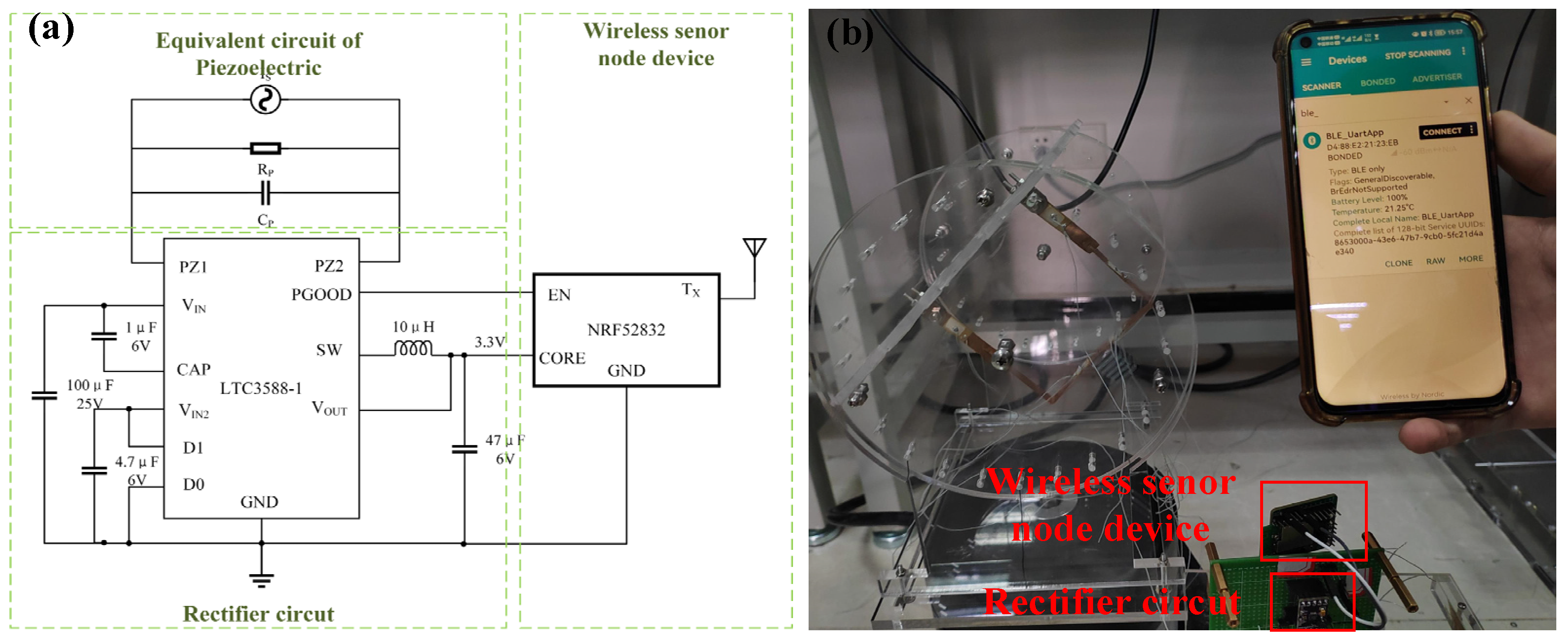
Table 1. The dimensions of components in U-shaped structure (Unit: mm).
Tabular array 1. The dimensions of components in U-shaped construction (Unit: mm).
| Components | Valid Length | Width | Thickness |
|---|---|---|---|
| PZT-5A | 12 | eight | 0.2 |
| Horizontal beam | 100 | x | 0.ii |
| Lower beam | 50 | x | 0.2 |
| Upper beam | 40 | 10 | 0.2 |
Table ii. Comparison of resonant frequencies from simulation and experiment (Unit: Hz).
Table two. Comparison of resonant frequencies from simulation and experiment (Unit of measurement: Hz).
| Orders | Measured | False | Departure |
|---|---|---|---|
| 1st | 2.six | two.26 | 0.34 |
| 2nd | 9.1 | 10.79 | 1.69 |
| third | 11.four | 13.89 | 2.35 |
Tabular array iii. Comparing of the proposed and some existing PVEHs.
Table 3. Comparing of the proposed and some existing PVEHs.
| Works | Excitations (1D/2D/3D) | Acc. (g) | Fre. (Hz) | Power (µW) | Volu. (mmthree) | NVPD (µW/(mm3giiHz)) |
|---|---|---|---|---|---|---|
| [34] | 1D | 0.041 | 27.v | 93 | 6300 | 0.3139 |
| [35] | 1D | i | 160 | 2490 | 880 | 0.0177 |
| [23] | 1D | 0.1 | 12 | 442 | 8400 | 0.4383 |
| [36] | 2D | 3 | 18 | 963.9 | 3120 | 0.00191 |
| [32] | 3D | 0.v | 23.seven | nine.2 | 4256 | 0.00036 |
| [30] | 3D | 0.008 | 4.56 | - | 982 | - |
| [28] | 3D | 0.v | 8 | 110.3 | 3480 | 0.0158 |
| [31] | 3D | 1 | ii.9 | 306 | 4507 | 0.0234 |
| This work | 3D | 0.5 | ii.five | 314 | 4586 | 0.1115 |
| Publisher'south Note: MDPI stays neutral with regard to jurisdictional claims in published maps and institutional affiliations. |
© 2022 by the authors. Licensee MDPI, Basel, Switzerland. This article is an open access commodity distributed under the terms and conditions of the Creative Commons Attribution (CC BY) license (https://creativecommons.org/licenses/by/4.0/).
Source: https://www.mdpi.com/2072-666X/13/3/396/htm
Postar um comentário for "A Review on Performance Enhancement Techniques for Ambient Vibration Energy Harvesters"